Toyota Tacoma (2015-2018) Service Manual: Removal
REMOVAL
PROCEDURE
1. REMOVE NO. 2 ENGINE UNDER COVER SUB-ASSEMBLY (w/ Off Road Package)
2. REMOVE NO. 1 ENGINE UNDER COVER SUB-ASSEMBLY
3. DRAIN ENGINE COOLANT
.gif)
4. REMOVE RADIATOR GRILLE
(See page )
5. REMOVE V-BANK COVER SUB-ASSEMBLY
6. REMOVE RADIATOR SUPPORT TO FRAME SEAL
7. REMOVE RADIATOR SIDE DEFLECTOR LH
|
(a) Remove the clip. |
|

(b) Disengage the 3 claws and remove the radiator side deflector LH.
8. REMOVE RADIATOR SIDE DEFLECTOR RH
|
(a) Remove the clip. |
|

(b) Disengage the 3 claws and remove the radiator side deflector RH.
9. REMOVE NO. 1 RADIATOR HOSE
|
(a) Slide the 2 hose clips and remove the No. 1 radiator hose from the water outlet and radiator assembly. |
|
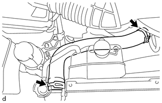
10. REMOVE NO. 2 RADIATOR HOSE
|
(a) Slide the hose clip and disconnect the No. 2 radiator hose from the water inlet with thermostat sub-assembly. |
|

|
(b) Slide the hose clip and remove the No. 2 radiator hose from the radiator assembly. |
|

11. DISCONNECT RADIATOR RESERVE TANK HOSE
|
(a) Disconnect the radiator reserve tank hose from the radiator assembly. |
|

12. DISCONNECT TRANSMISSION OIL COOLER HOSE (for Automatic Transmission)
(a) w/o Air Cooled Transmission Oil Cooler:
|
(1) Disengage the clamp to separate the 2 transmission oil cooler hoses from the fan shroud. |
|

(2) Slide the 2 hose clips and disconnect the 2 transmission oil cooler hoses from the radiator assembly.
(b) w/ Air Cooled Transmission Oil Cooler:
|
(1) Disengage the clamp to separate the 2 transmission oil cooler hoses from the fan shroud. |
|

(2) Slide the 2 hose clips and disconnect the 2 transmission oil cooler hoses from the radiator assembly.
13. REMOVE FAN SHROUD
|
(a) Loosen the 4 nuts holding the fan with fluid coupling. |
|

(b) Remove the fan and generator V belt (See page
).
|
(c) Remove the 2 bolts holding the fan shroud. |
|

(d) Remove the 4 nuts of the fan with fluid coupling, and then remove the fan shroud together with the fan with fluid coupling.
NOTICE:
Be careful not to damage the radiator core.
(e) Remove the fan pulley from the engine water pump assembly.
14. REMOVE RADIATOR ASSEMBLY
|
(a) Remove the 4 bolts. Text in Illustration
|
|

(b) Disengage the 2 hooks and remove the radiator assembly from the radiator support sub-assembly.
 Disassembly
DISASSEMBLY
PROCEDURE
1. REMOVE RADIATOR DRAIN COCK PLUG
(a) Remove the radiator drain cock plug from the radiator assembly.
(b) Remove the O-ring from the radiator drain cock plug.
2. REMOVE RAD ...
 Inspection
INSPECTION
PROCEDURE
1. INSPECT RADIATOR CORE SUB-ASSEMBLY
Check the core plate for damage.
Text in Illustration
*1
Core Plate
*2
Radiator Core
...
Other materials:
Components
COMPONENTS
ILLUSTRATION
*1
RADIATOR GRILLE
-
-
ILLUSTRATION
*A
for Type A
*B
for Type B
*C
for Type C
-
-
*1
MILLIMET ...
Navigation Receiver Assembly Communication Stop Mode
DESCRIPTION
Detection Item
Symptom
Trouble Area
Navigation Receiver Assembly Communication Stop Mode
Either condition is met:
Communication stop for "Display and Navigation (AVN1)" is indicated
on the "C ...
Disassembly
DISASSEMBLY
PROCEDURE
1. INSPECT PROPELLER SHAFT UNIVERSAL JOINT SPIDER BEARING
(a) Check the spider bearings for wear and damage.
(b) Check each spider bearings axial play by turning the yoke while holding the
shaft tightly.
Maximum bearing axial play:
0 to 0.05 mm (0 to 0.00197 in.)
If t ...