Toyota Tacoma (2015-2018) Service Manual: Disassembly
DISASSEMBLY
PROCEDURE
1. REMOVE BRAKE ACTUATOR BRACKET NO. 1

(a) Using a hexagon wrench (5 mm), remove the screw and brake actuator bracket No. 1.
|
(b) Using a screwdriver, remove the fluid level warning switch connector. |
|

2. REMOVE BRAKE MASTER CYLINDER RESERVOIR SUB-ASSEMBLY

(a) Remove the screw from the master cylinder reservoir.
|
(b) Using a pin punch and hammer, remove the pin from the master cylinder reservoir. |
|

(c) Pull out the master cylinder reservoir.
(d) Remove the 3 grommets.
(e) Remove the cap.
3. REMOVE BRAKE ACTUATOR HOSE NO. 1
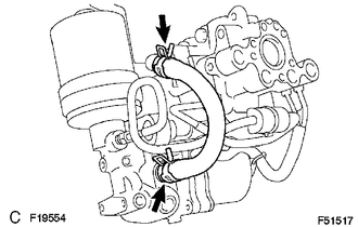
(a) Using needle-nose pliers, slide the 2 clips.
(b) Remove the brake actuator hose.
4. REMOVE BRAKE ACTUATOR TUBE NO. 1

(a) Using a union nut wrench, remove the brake actuator tube No. 1.
5. REMOVE BRAKE BOOSTER WITH ACCUMULATOR PUMP ASSEMBLY

(a) Using a screwdriver, remove the 2 plugs.
|
(b) Remove the 2 screws and pull the wire harness. |
|

|
(c) Using a screwdriver, remove the clip. |
|

|
(d) Remove the brake booster w/ accumulator pump assembly. |
|

|
(e) Using a hexagon wrench (4 mm), remove the 2 pins. |
|

(f) Remove the 2 bushes and 2 collars from the brake booster with accumulator pump assembly.
6. REMOVE BRAKE ACTUATOR BRACKET

(a) Using a hexagon wrench (5 mm), remove the screw and brake actuator bracket.
7. REMOVE BRAKE BOOSTER PUMP BRACKET

(a) Using a hexagon wrench (5 mm), remove the 2 screws and brake booster pump bracket.
(b) Remove the bush from the brake booster pump bracket.
8. REMOVE MASTER CYLINDER PUSH ROD CLEVIS
(a) Loosen the lock nut on the brake master cylinder side, and then remove the rod operating adapter and lock nut.
(b) Loosen the lock nut on the rod operating adapter, and then remove the push rod clevis and lock nut.
9. REMOVE MASTER CYLINDER BOOT
10. REMOVE PISTON

(a) Which pressing in the piston with a screwdriver, use a pin or equivalent to push the C-ring from the hole in the master cylinder body. Then remove the snap ring with another screwdriver.
(b) Remove the piston by pulling it straight out, not at an angle.
NOTICE:
- If the piston is pulled out at an angle, there is a possibility that the cylinder bore could be damaged.
- Be careful not to damage the rubber lips on the piston when reassembling.
11. REMOVE MASTER CYLINDER SOLENOID

(a) Remove the 6 bolts.
(b) Remove the master cylinder solenoid and the gasket.
12. REMOVE BRAKE BOOSTER ACCUMULATOR ASSEMBLY

(a) Place the brake booster with accumulator pump assembly in a vise with a cloth.
(b) Using a socket wrench (17 mm), remove the brake booster accumulator.
(c) Remove the brake booster accumulator pipe, compression spring and O-ring.
 On-vehicle Inspection
ON-VEHICLE INSPECTION
PROCEDURE
1. INSPECT BRAKE MASTER CYLINDER FLUID PRESSURE CHANGE
(a) Inspect the battery positive voltage.
Battery positive voltage:
10 to 14 V
(b) Turn the ignition switc ...
 Removal
REMOVAL
CAUTION / NOTICE / HINT
NOTICE:
Before starting the work, make sure that the ignition switch is off
and depress the brake pedal more than 20 times.
As high pressure is appli ...
Other materials:
Ignition Coil And Spark Plug
Components
COMPONENTS
ILLUSTRATION
Installation
INSTALLATION
PROCEDURE
1. INSTALL SPARK PLUG
HINT:
Perform "Inspection After Repairs" after replacing the spark plug (See page
).
(a) Install the 6 spark plugs.
Torque:
18 N·m {184 kgf·cm, 13 ft·lbf}
2. INSTALL IGNITIO ...
Driver Side Door Entry Lock Function does not Operate
DESCRIPTION
If the entry lock function does not operate for the driver door only, but the
entry unlock function operates, the request code is being transmitted properly from
the driver door. In this case, there may be a problem related to the front door
outside handle assembly LH (lock sensor ...
Brake
General Maintenance
GENERAL MAINTENANCE
PROCEDURE
1. INSPECT BRAKE LINE PIPES AND HOSES
HINT:
Work in a well-lighted area. Turn the front wheels fully to the right or left
before beginning.
(a) Check all the brake lines and hoses for:
Damage
Wear
Deformation
Cracks
...
