Toyota Tacoma (2015-2018) Service Manual: Removal
REMOVAL
PROCEDURE
1. REMOVE FRONT NO. 2 EXHAUST PIPE ASSEMBLY (for 2GR-FKS)
.gif)
2. REMOVE PROPELLER SHAFT HEAT INSULATOR BRACKET SUB-ASSEMBLY

(a) Remove the 2 bolts and propeller shaft heat insulator bracket.
3. REMOVE FRONT PROPELLER SHAFT ASSEMBLY

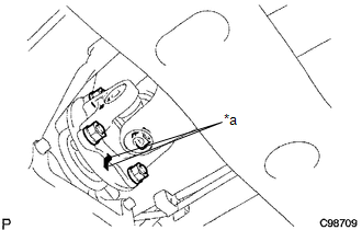
(a) Place matchmarks on the propeller shaft flange and differential flange.
Text in Illustration|
*a |
Matchmark |
(b) Remove the 4 nuts, 4 bolts, 4 washers and front propeller shaft.
|
(c) Place matchmarks on the propeller shaft flange and transfer flange. Text in Illustration
|
|
(d) Remove the 4 nuts, 4 washers and front propeller shaft.
 Components
COMPONENTS
ILLUSTRATION
...
 Disassembly
DISASSEMBLY
PROCEDURE
1. INSPECT FRONT PROPELLER SHAFT UNIVERSAL JOINT SPIDER BEARING
(a) Check the spider bearings for wear and damage.
(b) Check each spider bearing's axial play by turning t ...
Other materials:
ECU Power Source Circuit
WIRING DIAGRAM
CAUTION / NOTICE / HINT
NOTICE:
Inspect the fuses for circuits related to this system before performing the following
inspection procedure.
PROCEDURE
1.
INSPECT BATTERY
(a) Check the battery voltage.
Standard voltage:
11 to 14 V
NG
...
Taillight Relay Circuit
DESCRIPTION
The main body ECU (multiplex network body ECU) controls the operation of the
TAIL relay.
WIRING DIAGRAM
CAUTION / NOTICE / HINT
NOTICE:
Inspect the fuses for circuits related to this system before performing
the following inspection procedure.
If the main body EC ...
Using the AUX port
To use the AUX port, connect a portable player, then select ŌĆ£AUXŌĆØ on the ŌĆ£Select
Audio SourceŌĆØ screen.
Connecting a portable audio player
■Operating portable audio players connected to the multimedia system
The volume can be adjusted using the vehicleŌĆÖs audio controls. All other ...
