Toyota Tacoma (2015-2018) Service Manual: Removal
REMOVAL
PROCEDURE
1. REMOVE FRONT PILLAR GARNISH LH
(See page .gif) )
)
2. REMOVE ASSIST GRIP SUB-ASSEMBLY
(See page )
3. REMOVE FRONT PILLAR GARNISH RH
(See page )
4. REMOVE NO. 1 INSTRUMENT PANEL SPEAKER PANEL SUB-ASSEMBLY
(See page )
5. REMOVE NO. 2 INSTRUMENT PANEL SPEAKER PANEL SUB-ASSEMBLY
(See page )
6. REMOVE FRONT NO. 2 SPEAKER ASSEMBLY LH
(a) Remove the 2 bolts.
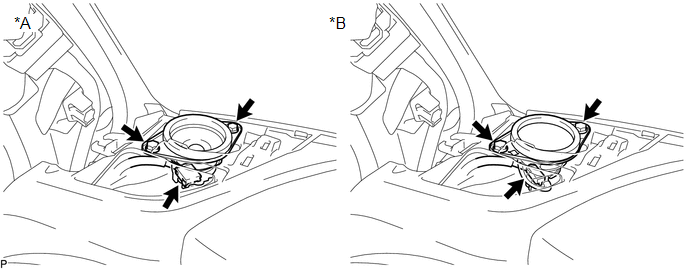 Text in Illustration
|
*A |
w/o Amplifier Box Speaker Assembly |
*B |
w/ Amplifier Box Speaker Assembly |
(b) Disconnect the connector to remove the front No. 2 speaker assembly LH.
NOTICE:
Do not touch the cone part of the front No. 2 speaker assembly LH.
7. REMOVE FRONT NO. 2 SPEAKER ASSEMBLY RH
(a) Remove the 2 bolts.
 Text in Illustration
|
*A |
w/o Amplifier Box Speaker Assembly |
*B |
w/ Amplifier Box Speaker Assembly |
(b) Disconnect the connector to remove the front No. 2 speaker assembly RH.
NOTICE:
Do not touch the cone part of the front No. 2 speaker assembly RH.
 Components
COMPONENTS
ILLUSTRATION
ILLUSTRATION
...
 Inspection
INSPECTION
PROCEDURE
1. INSPECT FRONT NO. 2 SPEAKER ASSEMBLY
(a) When there is a malfunction such as noise from a speaker or no sound at all,
replace the speaker with a new one and check that the ...
Other materials:
Dtc Check / Clear
DTC CHECK / CLEAR
1. DTC CHECK / CLEAR (when Using Techstream)
(a) Check for DTCs.
(1) Connect the Techstream to the DLC3.
(2) Turn the ignition switch to ON.
(3) Turn the Techstream on.
(4) Enter the following menus: Chassis / ABS/VSC/ TRAC / Trouble Codes.
(5) Read the DTCs by following the ...
System Diagram
SYSTEM DIAGRAM
Communication Table
Sender
Receiver
Signal
Communication Method
Power window regulator master switch assembly*1
Main Body ECU (Multiplex Network Body ECU)
Door control switch signal
...
Customize Parameters
CUSTOMIZE PARAMETERS
PROCEDURE
1. CUSTOMIZE AIR CONDITIONING SYSTEM
(a) Customizing with the Techstream
NOTICE:
When the customer requests a change in a function, first make sure that
the function can be customized.
Be sure to make a note of the current settings before customizi ...
