Toyota Tacoma (2015-2018) Service Manual: Removal
REMOVAL
PROCEDURE
1. REMOVE FRONT NO. 2 EXHAUST PIPE ASSEMBLY (for 2GR-FKS)
.gif)
2. REMOVE PROPELLER SHAFT HEAT INSULATOR BRACKET SUB-ASSEMBLY

(a) Remove the 2 bolts and propeller shaft heat insulator bracket.
3. REMOVE FRONT PROPELLER SHAFT ASSEMBLY

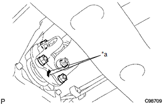
(a) Place matchmarks on the propeller shaft flange and differential flange.
Text in Illustration|
*a |
Matchmark |
(b) Remove the 4 nuts, 4 bolts, 4 washers and front propeller shaft.
|
(c) Place matchmarks on the propeller shaft flange and transfer flange. Text in Illustration
|
|
(d) Remove the 4 nuts, 4 washers and front propeller shaft.
 Components
COMPONENTS
ILLUSTRATION
...
 Disassembly
DISASSEMBLY
PROCEDURE
1. INSPECT FRONT PROPELLER SHAFT UNIVERSAL JOINT SPIDER BEARING
(a) Check the spider bearings for wear and damage.
(b) Check each spider bearing's axial play by turning t ...
Other materials:
Inspection
INSPECTION
PROCEDURE
1. INSPECT COUNTER GEAR
(a) Using a dial indicator and 2 V-blocks, measure the counter gear runout.
Maximum runout:
0.03 mm (0.00118 in.)
If the runout is more than the maximum, replace the counter gear.
HINT:
Measure the 3 areas shown in the illust ...
Dtc Check / Clear
DTC CHECK / CLEAR
1. DTC CHECK/CLEAR (When Using Techstream)
(a) Check the DTC.
(1) Turn the ignition switch off.
(2) Connect the Techstream to the DLC3.
(3) Turn the ignition switch to ON.
(4) Turn the Techstream on.
(5) Read the DTCs following the prompts on the Techstream screen. Enter the ...
Diagnostic Trouble Code Chart
DIAGNOSTIC TROUBLE CODE CHART
Steering Lock System
DTC Code
Detection Item
See page
B2781
Open / Short in Steering Lock ECU
B2782
Power Source Control ECU Malfunction
...
