Toyota Tacoma (2015-2018) Service Manual: Disassembly
DISASSEMBLY
PROCEDURE
1. INSPECT FRONT PROPELLER SHAFT UNIVERSAL JOINT SPIDER BEARING
(a) Check the spider bearings for wear and damage.
(b) Check each spider bearing's axial play by turning the yoke while holding the shaft tightly.
Maximum bearing axial play:
0 to 0.05 mm (0 to 0.002 in.)
2. REMOVE FRONT PROPELLER SHAFT UNIVERSAL JOINT SPIDER BEARING

(a) Place matchmarks on the propeller shaft and flange yoke.
Text in Illustration|
*a |
Matchmark |
|
(b) Using a brass bar and a hammer, slightly tap in the spider bearing outer races. |
|
(c) Using needle-nose pliers, remove the 4 snap rings from the grooves.
|
(d) Using SST, push the spider bearing out of the propeller shaft. SST: 09332-25010 HINT: Sufficiently raise the part indicated by (A) so that it does not come into contact with the spider bearing. |
|

|
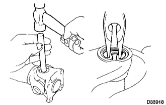
(e) Clamp the spider bearing outer race in a vise and tap off the propeller shaft with a hammer. HINT: Remove the bearing on the opposite side in the same procedure. Text in Illustration
NOTICE: Do not tap the shaft. |
|

|
(f) Install the 2 removed spider bearing outer races onto the spider, and clamp them in a vise. |
|

(g) Using SST, push the bearing out of the yoke.
SST: 09332-25010
HINT:
Sufficiently raise the part indicated by (A) so that it does not come into contact with the bearing.
|
(h) Clamp the outer bearing race in a vise and tap off the flange yoke with a hammer. Text in Illustration
|
|

(i) Remove the spider.
 Removal
REMOVAL
PROCEDURE
1. REMOVE FRONT NO. 2 EXHAUST PIPE ASSEMBLY (for 2GR-FKS)
2. REMOVE PROPELLER SHAFT HEAT INSULATOR BRACKET SUB-ASSEMBLY
(a) Remove the 2 bolts and propeller shaft heat insu ...
 Inspection
INSPECTION
PROCEDURE
1. INSPECT FRONT PROPELLER SHAFT ASSEMBLY
(a) Using a dial indicator, check the propeller shaft runout.
Maximum runout:
0.6 mm (0.024 in.)
If the shaft runout is greater ...
Other materials:
Steering Pad Switch
Components
COMPONENTS
ILLUSTRATION
*1
STEERING PAD SWITCH ASSEMBLY
-
-
Removal
REMOVAL
PROCEDURE
1. REMOVE STEERING PAD
(See page )
2. REMOVE STEERING PAD SWITCH ASSEMBLY
(a) Disconnect the 2 connectors.
...
Pressure Control Solenoid "G" Circuit Open (P280713)
DESCRIPTION
Changing from 1st to 6th is performed by the ECM turning shift solenoid valves
SL1, SL2, SL3 and SL4 on and off. If an open or short circuit occurs in any of the
shift solenoid valves, the ECM controls the remaining normal shift solenoid valves
to allow the vehicle to be operated ...
Diagnostic Trouble Code Chart
DIAGNOSTIC TROUBLE CODE CHART
Smart Key System
DTC Code
Detection Item
See page
B27A1
Open in Driver Side Electrical Antenna Circuit
B27A5
Open in Front Floor Electrical Key Oscillator Circuit
...
