Toyota Tacoma (2015-2018) Service Manual: Rear Power Outlet Switch
Components
COMPONENTS
ILLUSTRATION

Inspection
INSPECTION
PROCEDURE
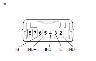
1. INSPECT MAIN SWITCH ASSEMBLY
(a) Check the main switch assembly.
|
(1) Measure the resistance according to the value(s) in the table below. Text in Illustration
Standard Resistance:
|
|
(b) Check the switch indicator.
(1) Apply battery voltage to the main switch assembly and check that the switch indicator illuminates.
OK:
|
Measurement Condition |
Switch Condition |
Specified Condition |
|---|---|---|
|
Battery positive (+) → 5 (IND+) Battery positive (-) → 2 (IND-) |
Always |
Illuminates |
OK:
|
Measurement Condition |
Switch Condition |
Specified Condition |
|---|---|---|
|
Battery positive (+) → 6 (IG) Battery positive (-) → 4 (IND) |
Always |
Illuminates |
- If the specified condition is not met, replace the main switch assembly.
Removal
REMOVAL
PROCEDURE
1. REMOVE INSTRUMENT PANEL LOWER FINISH PANEL SUB-ASSEMBLY RH
(See page .gif) )
)
2. REMOVE MAIN SWITCH ASSEMBLY
|
(a) Disengage the 2 claws to remove the main switch assembly. |
|

Installation
INSTALLATION
PROCEDURE
1. INSTALL MAIN SWITCH ASSEMBLY
(a) Engage the 2 claws to install the main switch assembly.
2. INSTALL INSTRUMENT PANEL LOWER FINISH PANEL SUB-ASSEMBLY RH
(See page .gif) )
)
 Rear Power Outlet Socket
Components
COMPONENTS
ILLUSTRATION
ILLUSTRATION
Installation
INSTALLATION
PROCEDURE
1. INSTALL POWER OUTLET SOCKET ASSEMBLY
(a) Install the clamp.
(b) Connect the connector.
...
 Voltage Inverter
Components
COMPONENTS
ILLUSTRATION
Inspection
INSPECTION
PROCEDURE
1. INSPECT VOLTAGE INVERTER ASSEMBLY
(a) Check the voltage inverter assembly.
(1) Measure the voltage according to the ...
Other materials:
Removal
REMOVAL
PROCEDURE
1. REMOVE NO. 2 ENGINE UNDER COVER SUB-ASSEMBLY (w/ Off Road Package)
2. REMOVE NO. 1 ENGINE UNDER COVER SUB-ASSEMBLY
3. DRAIN ENGINE COOLANT
4. REMOVE RADIATOR GRILLE
(See page )
5. REMOVE EXHAUST MANIFOLD SUB-ASSEMBLY RH
(See page )
6. REMOVE NO. 2 OIL COOLER INLET ...
Installation
INSTALLATION
PROCEDURE
1. INSTALL VACUUM WARNING SWITCH ASSEMBLY (for 2GR-FKS)
Click here
2. INSTALL BRAKE VACUUM CHECK VALVE ASSEMBLY (for 2TR-FE)
(a) Install a new grommet onto the brake booster assembly.
(b) Install the vacuum check val ...
Front Left Seat Heat Sensor Circuit (B14C1)
DESCRIPTION
Output to the front seat cushion heater assembly LH temperature sensor stops
if one of the following occurs: 1) the temperature sensor is open or shorted; or
2) the temperature sensor is damaged and its output value does not change.
DTC Code
DTC Detection Cond ...
