Toyota Tacoma (2015-2018) Service Manual: Lost Communication with Blind Spot Monitor Slave Module (U0232)
DESCRIPTION
This DTC is stored when the blind spot monitor sensor LH judges that there is a communication problem with the blind spot monitor sensor RH.
|
DTC Code |
DTC Detection Condition |
Trouble Area |
|---|---|---|
|
U0232 |
The blind spot monitor sensor LH cannot receive signals from the blind spot monitor sensor RH. |
|
WIRING DIAGRAM

CAUTION / NOTICE / HINT
NOTICE:
- When checking for DTCs, make sure that the blind spot monitor main switch assembly (warning canceling switch assembly) is on.
- Inspect the fuses for circuits related to this system before performing the following inspection procedure.
PROCEDURE
|
1. |
CHECK HARNESS AND CONNECTOR (BLIND SPOT MONITOR SENSOR LH - BLIND SPOT MONITOR SENSOR RH) |
(a) Disconnect the B12 blind spot monitor sensor LH connector.
(b) Disconnect the B13 blind spot monitor sensor RH connector.
(c) Measure the resistance according to the value(s) in the table below.
Standard Resistance:
|
Tester Connection |
Condition |
Specified Condition |
|---|---|---|
|
B12-1 (CA2P) - B13-1 (CA2P) |
Always |
Below 1 Ω |
|
B12-6 (CA2N) - B13-6 (CA2N) |
Always |
Below 1 Ω |
| NG | .gif) |
REPAIR OR REPLACE CAN LINE OR CONNECTOR |
|
.gif)
|
2. |
CHECK HARNESS AND CONNECTOR (BLIND SPOT MONITOR SENSOR RH - BATTERY AND BODY GROUND) |
|
(a) Disconnect the blind spot monitor sensor RH connector. |
|
(b) Measure the voltage according to the value(s) in the table below.
Standard Voltage:
|
Tester Connection |
Switch Condition |
Specified Condition |
|---|---|---|
|
B13-5 (BLB) - Body ground |
Ignition switch ON |
11 to 14 V |
|
Ignition switch off |
Below 1 V |
(c) Measure the resistance according to the value(s) in the table below.
Standard Resistance:
|
Tester Connection |
Condition |
Specified Condition |
|---|---|---|
|
B13-10 (BRGD) - Body ground |
Always |
Below 1 Ω |
|
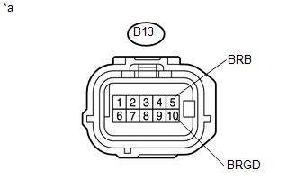
*a |
Front view of wire harness connector (to Blind Spot Monitor Sensor RH) |
| NG | |
REPAIR OR REPLACE HARNESS OR CONNECTOR |
|
|
3. |
CHECK BLIND SPOT MONITOR SENSOR RH |
(a) Replace the blind spot monitor sensor RH with a new or normally functioning
one (See page .gif) ).
).
(b) Clear the DTCs (See page ).
(c) Recheck for DTCs and check if the same DTC is output again (See page
).
OK:
No DTCs are output.
| OK | |
END (BLIND SPOT MONITOR SENSOR RH WAS DEFECTIVE) |
| NG | |
REPLACE BLIND SPOT MONITOR SENSOR LH |
 Software Incompatibility with Body Control Module "B" (U1331)
DESCRIPTION
This DTC is stored when the destination information of the main body ECU (multiplex
network body ECU) does not match that of the blind spot monitor sensors.
DTC Code
...
 Lost Communication with ECM / PCM "A" (U0100,U0126,U0129,U0142)
DESCRIPTION
These DTCs are stored if there is a malfunction in the CAN communication system
connected to the blind spot monitor sensor.
HINT:
If CAN communication system DTCs are stored, they may ...
Other materials:
Disassembly
DISASSEMBLY
PROCEDURE
1. REMOVE GENERATOR PULLEY
(a) Mount the generator assembly in the vise between aluminum plates.
NOTICE:
Do not overtighten the vise.
(b) Install SST 1-A to the generator pulley shaft.
Text in Illustration
*a
Hold
Turn
...
Terminals Of Ecu
TERMINALS OF ECU
1. BLIND SPOT MONITOR SENSOR LH (MASTER)
Terminal No.
(Symbol)
Wiring Color
Terminal Description
Condition
Specified Condition
B12-3 (BIND) - B12-10 (BLGD)
Y - W-B
Blind spot monitor ...
Removal
REMOVAL
PROCEDURE
1. REMOVE NO. 2 ENGINE UNDER COVER SUB-ASSEMBLY (w/ Off Road Package)
2. REMOVE NO. 1 ENGINE UNDER COVER SUB-ASSEMBLY
3. DRAIN ENGINE COOLANT
4. REMOVE RADIATOR GRILLE
(See page )
5. REMOVE V-BANK COVER SUB-ASSEMBLY
6. REMOVE RADIATOR SUPPORT TO FRAME SEAL
7. R ...
