Toyota Tacoma (2015-2018) Service Manual: Installation
INSTALLATION
PROCEDURE
1. INSPECT AND ADJUST BRAKE BOOSTER PUSH ROD
NOTICE:
The brake booster interior must not be a vacuum when adjusting the booster. Stop the engine and depress the brake pedal several times until there is no vacuum in the booster.
HINT:
Adjust the booster push rod when the master cylinder sub-assembly is replaced with a new one. Adjustment is not necessary when the master cylinder sub-assembly is reinstalled and the booster is replaced with a new one.
(a) Apply chalk to the tip of an accessory tool.
HINT:
The accessory tool is enclosed with a new brake master cylinder sub-assembly.
|
(b) Place the accessory tool on the brake booster assembly. |
|
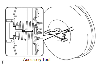
(c) Measure the clearance between the brake booster push rod and accessory tool.
Standard clearance:
0 mm (0 in.)
HINT:
Adjust the clearance in the following cases:
- If there is a clearance between the accessory tool and the shell of the brake booster (floating accessory tool), the push rod is protruding too far.
- If the chalk does not stick on the tip of the brake booster push rod, the push rod protrusion is insufficient.
|
(d) If the clearance is not as specified, adjust the push rod length by holding the rod using SST and turning the tip of the rod using a socket driver (7 mm). SST: 09737-00020 HINT: Check the push rod clearance again after adjustment. |
|

2. INSTALL BRAKE MASTER CYLINDER SUB-ASSEMBLY
(a) Install a new O-ring onto the brake master cylinder sub-assembly.
|
(b) Install the brake master cylinder sub-assembly with the 2 nuts onto the brake booster. Torque: 13 N·m {127 kgf·cm, 9 ft·lbf} |
|
.png)
|
(c) Using a union nut wrench, connect the 2 brake lines to the brake master cylinder sub-assembly. Torque: without union nut wrench : 20 N·m {199 kgf·cm, 14 ft·lbf} with union nut wrench : 18 N·m {187 kgf·cm, 13 ft·lbf} HINT:
|
|

|
(d) Connect the brake fluid level warning switch connector to the brake master cylinder sub-assembly. |
|
.png)
3. INSTALL CLUTCH RESERVOIR TUBE (for Manual Transmission)
|
(a) Connect the clutch reservoir tube to the reservoir. |
|
.png)
4. CONNECT CABLE TO NEGATIVE BATTERY TERMINAL
Torque:
5.4 N·m {55 kgf·cm, 48 in·lbf}
NOTICE:
When disconnecting the cable, some systems need to be initialized after the cable is reconnected.
Click here .gif)
5. FILL RESERVOIR WITH BRAKE FLUID
Click here
6. BLEED MASTER CYLINDER
Click here
7. BLEED BRAKE LINE
Click here
8. BLEED BRAKE ACTUATOR
Click here
9. INSPECT FLUID LEVEL IN RESERVOIR
Click here
10. INSPECT FOR BRAKE FLUID LEAK
11. INSPECT BRAKE PEDAL HEIGHT
Click here
12. INSPECT PEDAL FREE PLAY
Click here
13. INSPECT PEDAL RESERVE DISTANCE
Click here
 Removal
REMOVAL
CAUTION / NOTICE / HINT
NOTICE:
Release the vacuum from booster by depressing the brake pedal several times.
Then remove the brake master cylinder from brake booster.
PROCEDURE
1. PRECAU ...
 Reassembly
REASSEMBLY
PROCEDURE
1. INSTALL MASTER CYLINDER RESERVOIR GROMMET
(a) Apply lithium soap base glycol grease to 2 new grommets.
(b) Install the 2 grommets onto the brake master cylinder reservoir.
...
Other materials:
Back-up Power Source Circuit
DESCRIPTION
The back-up power source circuit for the air conditioning amplifier assembly
is shown below. Power is supplied even when the ignition switch is off. The power
is used for diagnostic trouble code memory, etc.
WIRING DIAGRAM
CAUTION / NOTICE / HINT
NOTICE:
Inspect the fuses for ...
Diagnostic Trouble Code Chart
DIAGNOSTIC TROUBLE CODE CHART
Smart Key System
DTC Code
Detection Item
See page
B27A1
Open in Driver Side Electrical Antenna Circuit
B27A5
Open in Front Floor Electrical Key Oscillator Circuit
...
Driver Side Door Entry Lock Function does not Operate
DESCRIPTION
If the entry lock function does not operate for the driver door only, but the
entry unlock function operates, the request code is being transmitted properly from
the driver door. In this case, there may be a problem related to the front door
outside handle assembly LH (lock sensor ...
