Toyota Tacoma (2015-2018) Service Manual: Data Signal Circuit between Stereo Jack Adapter and Extension Module
DESCRIPTION
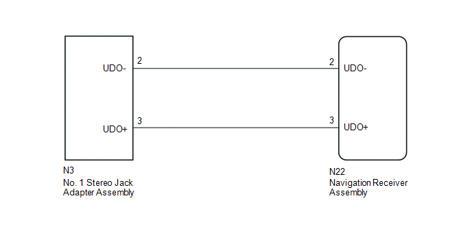
The No. 1 stereo jack adapter assembly sends the sound data signal or image data signal from a USB device to the navigation receiver assembly via this circuit.
WIRING DIAGRAM
PROCEDURE
|
1. |
CHECK HARNESS AND CONNECTOR (NAVIGATION RECEIVER ASSEMBLY - NO. 1 STEREO JACK ADAPTER ASSEMBLY) |
(a) Disconnect the N22 navigation receiver assembly connector.
(b) Disconnect the N3 No. 1 stereo jack adapter assembly connector.
(c) Measure the resistance according to the value(s) in the table below.
Standard Resistance:
|
Tester Connection |
Condition |
Specified Condition |
|---|---|---|
|
N3-2 (UDO-) - N22-2 (UDO-) |
Always |
Below 1 Ω |
|
N3-3 (UDO+) - N22-3 (UDO+) |
Always |
Below 1 Ω |
|
N3-2 (UDO-) - Body ground |
Always |
10 kΩ or higher |
|
N3-3 (UDO+) - Body ground |
Always |
10 kΩ or higher |
| OK | .gif) |
PROCEED TO NEXT SUSPECTED AREA SHOWN IN PROBLEM SYMPTOMS TABLE |
| NG | |
REPAIR OR REPLACE HARNESS OR CONNECTOR |
 Sound Signal Circuit between Radio Receiver and Stereo Component Amplifier
DESCRIPTION
The navigation receiver assembly sends a sound signal to the stereo component
amplifier assembly via this circuit.
The sound signal that has been sent is amplified by the stereo compon ...
 Sound Signal Circuit between Radio Receiver and Stereo Jack Adapter
DESCRIPTION
The No. 1 stereo jack adapter assembly sends the sound signal from an external
device to the navigation receiver assembly via this circuit.
If there is an open or short in the circuit, ...
Other materials:
Initialization
INITIALIZATION
1. RESET MEMORY
NOTICE:
Perform Reset Memory (AT initialization) when replacing the automatic
transmission assembly, transmission valve body assembly or any of the shift
solenoid valves.
Reset Memory can be performed only with the Techstream.
HINT:
The E ...
Reassembly
REASSEMBLY
CAUTION / NOTICE / HINT
HINT:
Use the same procedure for both the LH and RH sides.
The procedure described below is for the LH side.
PROCEDURE
1. INSTALL FOG LIGHT BULB
(a) Turn the fog light bulb in the direction indicated by the arrow in
the illust ...
Terminals Of Ecu
TERMINALS OF ECU
FORWARD RECOGNITION CAMERA
NOTICE:
DTCs may be output when connectors are disconnected during inspection.
Therefore, be sure to clear the DTCs using the Techstream once the inspection
has been completed.
Do not apply excessive force to the forward recognition ...
