Toyota Tacoma (2015-2018) Service Manual: System Diagram
SYSTEM DIAGRAM


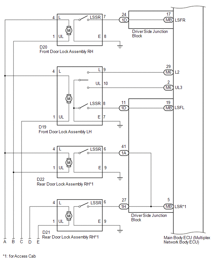
This is a detailed diagram related to the main body ECU (multiplex network body ECU).


|
Component |
Function |
|---|---|
|
Front door outside handle assembly LH |
Receives request signals from the certification ECU (smart key ECU assembly) via the built-in electrical key antenna (front door) and forms the vehicle exterior detection area. Uses the built-in touch sensor (lock sensor/unlock sensor) to detect the operation of the front door outside handle assembly and sends signals to the certification ECU (smart key ECU assembly). |
|
No. 1 indoor electrical key antenna assembly (front floor) No. 2 indoor electrical key antenna assembly (rear floor) |
Receives the request code from the certification ECU (smart key ECU assembly) and forms the vehicle interior detection area. |
|
Electrical key and TPMS receiver assembly |
Receives the smart key system code/wireless code sent from the electrical key transmitter sub-assembly and sends it to the certification ECU (smart key ECU assembly). |
|
Wireless door lock buzzer |
Sounds when warning functions operate in accordance with certification ECU (smart key ECU assembly) control. |
|
Electrical key transmitter sub-assembly |
Sends the ID code upon receiving a request signal. |
|
Certification ECU (smart key ECU assembly) |
Sends request codes to each electrical key antenna. Distinguishes and verifies the ID code from the electrical key transmitter sub-assembly and sends signals to each ECU in response to operated functions (controls entire system). Performs encryption code communication with the steering lock ECU (steering lock actuator or UPR bracket assembly) when ignition operations are performed. |
 Precaution
PRECAUTION
1. CAUTION REGARDING INTERFERENCE WITH ELECTRONIC DEVICES
CAUTION:
People with implantable cardiac pacemakers, cardiac resynchronization
therapy-pacemakers or implantable car ...
 How To Proceed With Troubleshooting
CAUTION / NOTICE / HINT
HINT:
Use these procedures to troubleshoot the smart key system (for Entry
Function).
*: Use the Techstream.
PROCEDURE
1.
VEHIC ...
Other materials:
Customize Parameters
CUSTOMIZE PARAMETERS
PROCEDURE
1. CHECK CERTIFICATION ECU (SMART KEY ECU ASSEMBLY)
HINT:
The following items can be customized.
NOTICE:
When the customer requests a change in a function, first make sure that
the function can be customized.
Record the current settings before cus ...
Acceleration Sensor Power Supply Voltage Malfunction (C1381)
DESCRIPTION
The skid control ECU (brake actuator assembly) receives signals from the yaw
rate and acceleration sensor (airbag sensor assembly) via the CAN communication
system.
The airbag sensor assembly has a built-in acceleration sensor and detects the
vehicle condition.
If there is troub ...
Diagnosis System
DIAGNOSIS SYSTEM
DIAGNOSIS FUNCTION
(a) The diagnosis function turns off the cruise control indicator, illuminates
the master warning light and displays a warning message when a malfunction is detected.
When a malfunction is detected in the dynamic radar cruise control system, DTCs
are store ...
