Toyota Tacoma (2015-2018) Service Manual: Removal
REMOVAL
PROCEDURE
1. PRECAUTION
NOTICE:
After turning the ignition switch off, waiting time may be required before disconnecting the cable from the negative (-) battery terminal. Therefore, make sure to read the disconnecting the cable from the negative (-) battery terminal notices before proceeding with work.
Click here .gif)
2. DISCONNECT CABLE FROM NEGATIVE BATTERY TERMINAL
NOTICE:
When disconnecting the cable, some systems need to be initialized after the cable is reconnected.
Click here
3. REMOVE HEATED OXYGEN SENSOR
Click here
4. REMOVE TAIL EXHAUST PIPE ASSEMBLY
|
(a) Remove the 2 bolts to separate the tail exhaust pipe assembly. |
|
(b) Disconnect the 4 exhaust pipe supports to remove the tail exhaust pipe assembly.
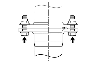
5. REMOVE CENTER EXHAUST PIPE ASSEMBLY
|
(a) Remove the 2 bolts and 2 compression springs. |
|
.png)
|
(b) Remove the 2 bolts to separate the center exhaust pipe assembly. |
|
.png)
(c) Disconnect the exhaust pipe support to remove the center exhaust pipe assembly.
6. REMOVE CENTER NO. 2 FLOOR HEAT INSULATOR SUB-ASSEMBLY (for 4WD)
|
(a) Remove the 3 nuts and center No. 2 floor heat insulator sub-assembly. |
|

7. REMOVE EXHAUST PIPE STOPPER BRACKET (for 4WD)
|
(a) Remove the 2 bolts and exhaust pipe stopper bracket. |
|

8. REMOVE FRONT NO. 2 EXHAUST PIPE ASSEMBLY
|
(a) Remove the 2 nuts to separate the front No. 2 exhaust pipe assembly from the exhaust manifold LH. |
|
.png)
(b) Disconnect the exhaust pipe support to remove the front No. 2 exhaust pipe assembly.
9. REMOVE FRONT EXHAUST PIPE ASSEMBLY
|
(a) Remove the 2 nuts and front exhaust pipe assembly. |
|
.png)
10. REMOVE MONOLITHIC CONVERTER PROTECTOR
|
(a) Remove the bolt and clamp. |
|

(b) Remove the 2 bolts, 2 nuts and upper monolithic converter protector and lower monolithic converter protector.
 Components
COMPONENTS
ILLUSTRATION
ILLUSTRATION
...
 Installation
INSTALLATION
PROCEDURE
1. REMOVE MONOLITHIC CONVERTER PROTECTOR
(a) Install the upper monolithic converter protector and lower monolithic converter
protector with the 2 bolts and 2 nuts.
Torque: ...
Other materials:
Disassembly
DISASSEMBLY
PROCEDURE
1. INSPECT CONNECTING ROD THRUST CLEARANCE
(a) Using a dial indicator, measure the thrust clearance while moving
the connecting rod back and forth.
Standard thrust clearance:
0.15 to 0.40 mm (0.00591 to 0.0157 in.)
Maximum thrust clearance:
0.50 ...
Front Radar Sensor (C1A10)
DESCRIPTION
C1A10 is output when there is an internal malfunction in the millimeter wave
radar sensor assembly.
DTC No.
Detection Item
DTC Detection Condition
Trouble Area
MIL
C1A10
Front Radar Sensor
W ...
Pressure Control Solenoid "G" Actuator Stuck Off (P28077F)
SYSTEM DESCRIPTION
The ECM uses the vehicle speed signal and signals from the transmission revolution
sensors (NT, SP2) to detect the actual gear (1st, 2nd, 3rd, 4th, 5th or 6th gear).
The ECM compares the actual gear with the shift schedule in the ECM memory to
detect mechanical problems of t ...
