Toyota Tacoma (2015-2018) Service Manual: Disassembly
DISASSEMBLY
CAUTION / NOTICE / HINT
NOTICE:
Do not try to remove the black nylon tube as it is welded to the fuel suction
tube assembly (See page .gif) ).
).
PROCEDURE
1. REMOVE FUEL SENDER GAUGE ASSEMBLY
2. REMOVE NO. 1 FUEL SUB-TANK
|
(a) Disconnect the 2 fuel pump connectors. |
|

(b) Disengage the clamp and disconnect the wire harness.
|
(c) Disengage the claw and 2 clamps and disconnect the jet pump nozzle. |
|

|
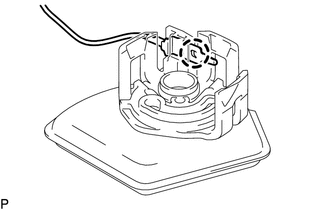
(d) Using a screwdriver with its tip wrapped with protective tape, disconnect the jet pump from the No. 1 fuel sub-tank. Text in Illustration
NOTICE: The O-ring is installed firmly between the jet pump and No. 1 fuel sub-tank. Therefore, the jet pump and No. 1 fuel sub-tank should be separated carefully using a screwdriver. |
|

|
(e) Disengage the 5 claws and remove the No. 1 fuel sub-tank. NOTICE: Do not damage the No. 1 fuel sub-tank. |
|

3. REMOVE FUEL PUMP FILTER
|
(a) Disengage the 3 claws and disconnect the fuel pump filter from the fuel filter case. |
|

|
(b) Disengage the claw and disconnect the fuel pump harness from the fuel pump filter. |
|
4. REMOVE FUEL PUMP
|
(a) Disengage the clamp and disconnect the wire harness. |
|

|
(b) Disengage the 2 claws and remove the No. 1 fuel suction support from the fuel filter case. |
|

|
(c) Remove the fuel pump from the fuel filter case. |
|

|
(d) Disconnect the fuel pump harness connector and remove the fuel pump harness from the fuel pump. |
|

|
(e) Remove the O-ring and fuel pump spacer from the fuel pump. Text in Illustration
NOTICE: Be careful not to damage the sealing surface. HINT: If the O-ring still remains in the fuel filter, remove it using a wire tip (1 mm diameter) that is formed as shown in the illustration. |
|

 Components
COMPONENTS
ILLUSTRATION
ILLUSTRATION
...
 Removal
REMOVAL
PROCEDURE
1. REMOVE FUEL TANK ASSEMBLY
Click here
2. DISCONNECT FUEL TANK MAIN TUBE SUB-ASSEMBLY
Click here
3. REMOVE FUEL PUMP GAUGE RETAINER
NOTICE:
Before performing these proce ...
Other materials:
Driver Side Door ECU Communication Stop (B2321)
DESCRIPTION
This DTC is stored when LIN communication between the front power window regulator
motor assembly LH and main body ECU (multiplex network body ECU) stops for 10 seconds
or more.
DTC No.
DTC Detection Condition
Trouble Area
B2321
...
Inspection
INSPECTION
PROCEDURE
1. INSPECT FRONT SEAT CUSHION HEATER ASSEMBLY
(a) Check the operation of the front seat cushion heater assembly.
(1) Apply battery voltage and check the operation of the front seat cushion
heater assembly.
OK:
Connection
...
License Plate Light Assembly
Components
COMPONENTS
ILLUSTRATION
Removal
REMOVAL
CAUTION / NOTICE / HINT
HINT:
Use the same procedure for both the LH and RH sides.
The procedure described below is for the LH side.
PROCEDURE
1. REMOVE LICENSE PLATE LIGHT ASSEMBLY
(a) Disconnect the con ...
