Toyota Tacoma (2015-2018) Service Manual: Cargo Light Circuit
DESCRIPTION
The main body ECU (multiplex network body ECU) receives a cargo light information signal from the deck light switch assembly and door courtesy light switch, and illuminates the cargo light.
WIRING DIAGRAM

CAUTION / NOTICE / HINT
NOTICE:
- Inspect the fuses for circuits related to this system before performing the following inspection procedure.
- If the main body ECU (multiplex network body ECU) is replaced, refer
to Registration (See page
.gif) ).*1
).*1
- *1: w/ Smart Key System
PROCEDURE
|
1. |
PERFORM ACTIVE TEST USING TECHSTREAM (CARGO LIGHT) |
(a) Connect the Techstream to the DLC3.
(b) Turn the ignition switch to ON.
(c) Turn the Techstream on.
(d) Enter the following menus: Body Electrical / Main Body / Active Test.
(e) Perform the Active Test according to the display on the Techstream.
Main Body ECU|
Tester Display |
Test Part |
Control Range |
Diagnostic Note |
|---|---|---|---|
|
Cargo Light |
Cargo light |
ON or OFF |
Deck light switch assembly is DOOR or on |
OK:
Cargo light turns on / turns off.
| OK | .gif) |
PROCEED TO NEXT CIRCUIT INSPECTION SHOWN IN PROBLEM SYMPTOMS TABLE |
|
.gif)
|
2. |
INSPECT CARGO RELAY |
(a) Remove the CARGO relay from the junction block assembly.
|
(b) Measure the resistance according to the value(s) in the table below. Standard Resistance:
|
|
.png)
| NG | |
REPLACE CARGO RELAY |
|
|
3. |
CHECK HARNESS AND CONNECTOR (CARGO FUSE - CARGO RELAY) |
(a) Measure the voltage according to the value(s) in the table below.
Standard Voltage:
|
Tester Connection |
Condition |
Specified Condition |
|---|---|---|
|
Relay terminal 1- Body ground |
Always |
11 to 14 V |
|
Relay terminal 3- Body ground |
Always |
11 to 14 V |
| NG | |
REPAIR OR REPLACE HARNESS OR CONNECTOR |
|
|
4. |
CHECK HARNESS AND CONNECTOR (CARGO RELAY - CENTER STOP LIGHT ASSEMBLY (CARGO LIGHT)) |
(a) Disconnect the C15 cargo light connector.
(b) Measure the resistance according to the value(s) in the table below.
Standard Resistance:
|
Tester Connection |
Condition |
Specified Condition |
|---|---|---|
|
Relay terminal 5 - C15-3 (DL) |
Always |
Below 1 Ω |
|
Relay terminal 3 - Body ground |
Always |
10 kΩ or higher |
|
C15-1 (E) - Body ground |
Always |
Below 1 Ω |
| NG | |
REPAIR OR REPLACE HARNESS OR CONNECTOR |
|
|
5. |
INSPECT CARGO LIGHT |
(a) Remove the cargo light (See page ).
(b) Inspect the cargo light (See page ).
| NG | |
REPLACE CARGO LIGHT |
|
|
6. |
INSPECT DECK LIGHT SWITCH ASSEMBLY |
(a) Remove the deck light switch assembly (See page
).
(b) Inspect the deck light switch assembly (See page
).
| NG | |
REPLACE DECK LIGHT SWITCH ASSEMBLY |
|
|
7. |
CHECK HARNESS AND CONNECTOR (DECK LIGHT SWITCH ASSEMBLY - CARGO RELAY AND BODY GROUND) |
(a) Disconnect the D35 deck light switch assembly connector.
(b) Remove the CARGO relay from the junction block assembly.
(c) Measure the resistance according to the value(s) in the table below.
Standard Resistance:
|
Tester Connection |
Switch Condition |
Specified Condition |
|---|---|---|
|
D35-5 (CCTY) - Relay terminal 2 |
Always |
Below 1 Ω |
|
D35-5 (CCTY) - Body ground |
Always |
10 kΩ or higher |
|
D35-7 (E) - Body ground |
Always |
Below 1 Ω |
| NG | |
REPAIR OR REPLACE HARNESS OR CONNECTOR |
|
|
8. |
CHECK HARNESS AND CONNECTOR (DECK LIGHT SWITCH ASSEMBLY - DRIVER SIDE JUNCTION BLOCK AND MAIN BODY ECU) |
(a) Disconnect the D35 deck light switch assembly connector.
(b) Disconnect the 1A driver side junction block connector.
(c) Disconnect the M6 main body ECU (multiplex network body ECU) connector.
(d) Measure the resistance according to the value(s) in the table below.
Standard Resistance:
|
Tester Connection |
Condition |
Specified Condition |
|---|---|---|
|
D35-9 (CGON) - 1A-40 |
Always |
Below 1 Ω |
|
D35-9 (CGON) - Body ground |
Always |
10 kΩ or higher |
|
D35-10 (CGLP) - M6-23 (CGSW) |
Always |
Below 1 Ω |
|
D35-10 (CGLP) - Body ground |
Always |
10 kΩ or higher |
| NG | |
REPAIR OR REPLACE HARNESS OR CONNECTOR |
|
|
9. |
INSPECT DRIVER SIDE JUNCTION BLOCK |
(a) Remove the driver side junction block (See page
).
|
(b) Remove the main body ECU (multiplex network body ECU) from the driver side junction block. |
|
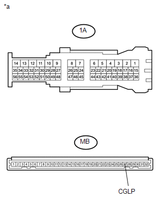
(c) Measure the resistance according to the value(s) in the table below.
Standard Resistance:
|
Tester Connection |
Condition |
Specified Condition |
|---|---|---|
|
1A-40 - MB-27 (CGLP) |
Always |
Below 1 Ω |
|
*a |
Component without harness connected (Driver Side Junction Block) |
| OK | |
REPLACE MAIN BODY ECU (MULTIPLEX NETWORK BODY ECU) |
| NG | |
REPLACE DRIVER SIDE JUNCTION BLOCK |
 Taillight Relay Circuit
DESCRIPTION
The main body ECU (multiplex network body ECU) controls the operation of the
TAIL relay.
WIRING DIAGRAM
CAUTION / NOTICE / HINT
NOTICE:
Inspect the fuses for circuits rela ...
 Door Unlock Detection Switch Circuit
DESCRIPTION
The main body ECU (multiplex network body ECU) detects the condition of each
door unlock detection switch.
WIRING DIAGRAM
CAUTION / NOTICE / HINT
NOTICE:
If the main body ECU (mul ...
Other materials:
Auto Down Operation does not Fully Open Power Window (Catch Protection Function
is Activated)
DESCRIPTION
If a front door glass or the power window regulator motor assembly (for driver
door) or power window regulator motor assembly (front passenger door) does not operate
smoothly, the catch protection function may be triggered automatically, resulting
in the auto down operation being ...
Inspection
INSPECTION
PROCEDURE
1. INSPECT COUNTER GEAR
(a) Using a dial indicator and 2 V-blocks, measure the counter gear runout.
Maximum runout:
0.03 mm (0.00118 in.)
If the runout is more than the maximum, replace the counter gear.
HINT:
Measure the 3 areas shown in the illust ...
On-vehicle Inspection
ON-VEHICLE INSPECTION
PROCEDURE
1. INSPECT CURTAIN SHIELD AIRBAG ASSEMBLY (for Vehicle not Involved in Collision)
(a) Perform a Diagnostic System Check (See page
).
(b) With the curtain shield airbag installed on the vehicle, perform
a visual check. If any of the defects mention ...
