Toyota Tacoma (2015-2018) Service Manual: System Diagram
SYSTEM DIAGRAM
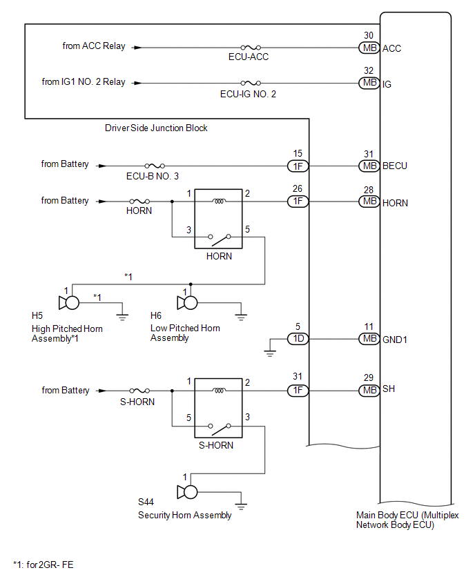


 System Description
SYSTEM DESCRIPTION
1. OUTLINE OF THEFT DETERRENT SYSTEM
The theft deterrent system can be set/canceled by locking/unlocking
the doors using the following operation:
Entry lo ...
 Diagnosis System
DIAGNOSIS SYSTEM
1. CHECK DLC3
(a) Check the DLC3 (See page ).
2. INSPECT BATTERY VOLTAGE
(a) Measure the battery voltage.
Standard Voltage:
11 to 14 V
If the voltage is below 11 V, replace t ...
Other materials:
Installation
INSTALLATION
PROCEDURE
1. INSTALL EXHAUST MANIFOLD SUB-ASSEMBLY LH
(a) Install a new gasket to the cylinder head LH.
NOTICE:
Be careful of the installation direction.
(b) Temporarily install the exhaust manifold sub-assembly LH with the 4 nuts.
(c) Tighten the 4 nuts in the sequenc ...
Rear Speed Sensor RH Malfunction (C1403,C1404)
DESCRIPTION
The speed sensor detects wheel speed and sends the appropriate signals to the
skid control ECU (brake actuator assembly). These signals are used for brake control.
The speed sensor rotors have rows of alternating N and S magnetic poles and their
magnetic fields change when the roto ...
How To Proceed With Troubleshooting
CAUTION / NOTICE / HINT
HINT:
Use the following procedures to troubleshoot the cruise control system.
*: Use the Techstream.
PROCEDURE
1.
VEHICLE BROUGHT TO WORKSHOP
NEXT
...
