Toyota Tacoma (2015-2018) Service Manual: Removal
REMOVAL
PROCEDURE
1. REMOVE CLUTCH MASTER CYLINDER ASSEMBLY
(See page .gif) )
)
2. REMOVE TURN OVER SPRING SEAT COMPRESSION SPRING
|
(a) Remove the compression spring. |
|

3. REMOVE CLUTCH PEDAL SUB-ASSEMBLY
|
(a) Remove the bolt and nut. |
|

(b) Remove the clutch pedal sub-assembly from the clutch pedal support.
4. REMOVE CLUTCH PEDAL SPRING HOLDER
|
(a) Remove the clutch pedal spring holder from the clutch pedal support. |
|

5. REMOVE CLUTCH PEDAL PAD
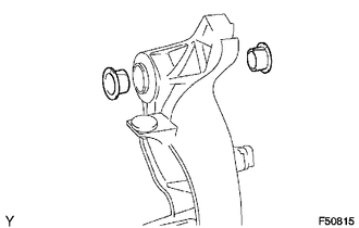
6. REMOVE CLUTCH PEDAL BUSH
|
(a) Remove the 2 bushes from the clutch pedal sub-assembly. |
|
7. REMOVE CLUTCH PEDAL SHAFT COLLAR
|
(a) Remove the clutch pedal shaft collar from the clutch pedal sub-assembly. |
|

8. REMOVE CLUTCH PEDAL NO.1 CUSHION
|
(a) Using needle-nose pliers, remove the clutch pedal No. 1 cushion from the clutch pedal sub-assembly. |
|

 Components
COMPONENTS
ILLUSTRATION
...
 Adjustment
ADJUSTMENT
PROCEDURE
1. INSPECT AND ADJUST CLUTCH PEDAL
(a) Fold back the floor carpet.
(b) Check that the pedal height is correct.
Text in Illustration
*a
...
Other materials:
Terminals Of Ecu
TERMINALS OF ECU
NOTICE:
DTCs may be output when connectors are disconnected during inspection.
Therefore, be sure to clear the DTCs using the Techstream once the inspection
has been completed.
Do not apply excessive force to the f5 forward recognition camera connector.
...
Lost Communication with ECM / PCM "A" (U0100,U0125,U0126,U0129)
DESCRIPTION
These DTCs are stored when a communication malfunction occurs between ECUs that
perform pre-collision system control.
DTC No.
Detection Item
DTC Detection Condition
Trouble Area
U0100
Lost Communication with ECM ...
Transfer Shift Motor Control Circuit High (P17AA)
DESCRIPTION
This DTC is output when a short to B+ in the transfer shift motor and A.D.D.
shift motor drive circuit is detected.
DTC No.
Detection Item
DTC Detection Condition
Trouble Area
P17AA
Transfer Shift Motor Control C ...
