Toyota Tacoma (2015-2018) Service Manual: Fuel Pressure Sensor
Components
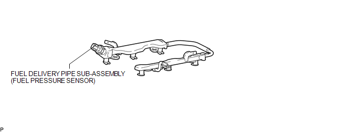
COMPONENTS
ILLUSTRATION
Inspection
INSPECTION
PROCEDURE
1. INSPECT FUEL DELIVERY PIPE SUB-ASSEMBLY (FUEL PRESSURE SENSOR)
NOTICE:
- Do not remove the fuel pressure sensor from the fuel delivery pipe sub-assembly.
- If a fuel pressure sensor is removed, replace the fuel delivery pipe sub-assembly with a new one.
(a) Remove the fuel delivery pipe sub-assembly (See page
.gif) ).
).
(b) Check the fuel pressure sensor output voltage.
|
(1) Apply 5 V between terminals 1 (VC) and 3 (E2). Text in Illustration
NOTICE:
HINT: If a stable power supply is not available, use 4 1.2 V nickel-metal hydride batteries or equivalent. |
|

|
(2) Measure the voltage between terminals. Text in Illustration
Standard Voltage:
If the result is not as specified, replace the fuel delivery pipe sub-assembly. |
|

(c) Install the fuel delivery pipe sub-assembly (See page
).
Installation
INSTALLATION
CAUTION / NOTICE / HINT
HINT:
Perform "Inspection After Repairs" after replacing the fuel delivery pipe sub-assembly
(fuel pressure sensor) (See page .gif) ).
).
PROCEDURE
1. INSTALL FUEL DELIVERY PIPE SUB-ASSEMBLY (FUEL PRESSURE SENSOR)
(See page )
NOTICE:
- Do not remove the fuel pressure sensor from the fuel delivery pipe sub-assembly.
- If a fuel pressure sensor is removed, replace the fuel delivery pipe sub-assembly (fuel pressure sensor) with a new one.
HINT:
Perform "Inspection After Repairs" after replacing the fuel delivery pipe sub-assembly
(fuel pressure sensor) (See page ).
Removal
REMOVAL
PROCEDURE
1. REMOVE FUEL DELIVERY PIPE SUB-ASSEMBLY (FUEL PRESSURE SENSOR)
(See page .gif) )
)
NOTICE:
- Do not remove the fuel pressure sensor from the fuel delivery pipe sub-assembly.
- If a fuel pressure sensor is removed, replace the fuel delivery pipe sub-assembly (fuel pressure sensor) with a new one.
 Fuel Main Valve
Components
COMPONENTS
ILLUSTRATION
Removal
REMOVAL
PROCEDURE
1. REMOVE FUEL SUCTION TUBE WITH PUMP AND GAUGE ASSEMBLY
(See page )
2. REMOVE FUEL SENDER GAUGE ASSEMBLY
3. REMOVE NO. ...

Other materials:
TRAC OFF Indicator Light does not Come ON
DESCRIPTION
Refer to TRAC OFF Indicator Light Remains ON (See page
).
WIRING DIAGRAM
Refer to TRAC OFF Indicator Light Remains ON (See page
).
CAUTION / NOTICE / HINT
NOTICE:
When replacing the skid control ECU (master cylinder solenoid), perform
calibration (See page
).
...
Removal
REMOVAL
PROCEDURE
1. REMOVE FUEL TANK ASSEMBLY
Click here
2. DISCONNECT FUEL TANK MAIN TUBE SUB-ASSEMBLY
Click here
3. REMOVE FUEL PUMP GAUGE RETAINER
NOTICE:
Before performing these procedures, first cover the connectors and tube joints
of the fuel suction tube with pump and gauge ass ...
Compass (vehicles with auto anti-glare inside rear view mirror)
The compass on the inside rear view mirror indicates the direction in which
the vehicle is heading.
■ Operation
Type A
To turn the compass on or off, press the button.
Type B
■ Displays and directions
Calibrating the compass
The direction display deviates from the true ...
