Toyota Tacoma (2015-2018) Service Manual: Disassembly
DISASSEMBLY
CAUTION / NOTICE / HINT
NOTICE:
Do not try to remove the black nylon tube as it is welded to the fuel suction
tube assembly (See page .gif) ).
).
PROCEDURE
1. REMOVE FUEL SENDER GAUGE ASSEMBLY
2. REMOVE NO. 1 FUEL SUB-TANK
|
(a) Disconnect the 2 fuel pump connectors. |
|

(b) Disengage the clamp and disconnect the wire harness.
|
(c) Disengage the claw and 2 clamps and disconnect the jet pump nozzle. |
|

|
(d) Using a screwdriver with its tip wrapped with protective tape, disconnect the jet pump from the No. 1 fuel sub-tank. Text in Illustration
NOTICE: The O-ring is installed firmly between the jet pump and No. 1 fuel sub-tank. Therefore, the jet pump and No. 1 fuel sub-tank should be separated carefully using a screwdriver. |
|

|
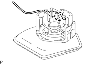
(e) Disengage the 5 claws and remove the No. 1 fuel sub-tank. NOTICE: Do not damage the No. 1 fuel sub-tank. |
|

3. REMOVE FUEL PUMP FILTER
|
(a) Disengage the 3 claws and disconnect the fuel pump filter from the fuel filter case. |
|

|
(b) Disengage the claw and disconnect the fuel pump harness from the fuel pump filter. |
|
4. REMOVE FUEL PUMP
|
(a) Disengage the clamp and disconnect the wire harness. |
|

|
(b) Disengage the 2 claws and remove the No. 1 fuel suction support from the fuel filter case. |
|

|
(c) Remove the fuel pump from the fuel filter case. |
|

|
(d) Disconnect the fuel pump harness connector and remove the fuel pump harness from the fuel pump. |
|

|
(e) Remove the O-ring and fuel pump spacer from the fuel pump. Text in Illustration
NOTICE: Be careful not to damage the sealing surface. HINT: If the O-ring still remains in the fuel filter, remove it using a wire tip (1 mm diameter) that is formed as shown in the illustration. |
|

 Components
COMPONENTS
ILLUSTRATION
ILLUSTRATION
...
 Removal
REMOVAL
PROCEDURE
1. REMOVE FUEL TANK ASSEMBLY
Click here
2. DISCONNECT FUEL TANK MAIN TUBE SUB-ASSEMBLY
Click here
3. REMOVE FUEL PUMP GAUGE RETAINER
NOTICE:
Before performing these proce ...
Other materials:
How To Proceed With Troubleshooting
CAUTION / NOTICE / HINT
HINT:
Use the following procedures to troubleshoot the steering lock system.
*: Use the Techstream.
PROCEDURE
1.
VEHICLE BROUGHT TO WORKSHOP
NEXT
...
Air conditioning system
Adjusting the settings
■ Adjusting the temperature setting
Turn the temperature control dial clockwise (warm) or counterclockwise (cool).
If is not pressed, the system will
blow ambient temperature air or heated air.
For quick cooling, turn the temperature control dial to the MAX A/C ...
Crankshaft Position Sensor "A" Signal Stuck in Range (P03352A,P033531)
DESCRIPTION
The crankshaft position sensor system consists of a crankshaft position sensor
plate and a pickup coil. The crankshaft position sensor plate has 34 teeth and is
installed to the crankshaft. The pickup coil is made of wound copper wire, an iron
core and a magnet. The crankshaft pos ...
