Toyota Tacoma (2015-2018) Service Manual: Clutch Accumulator
Components
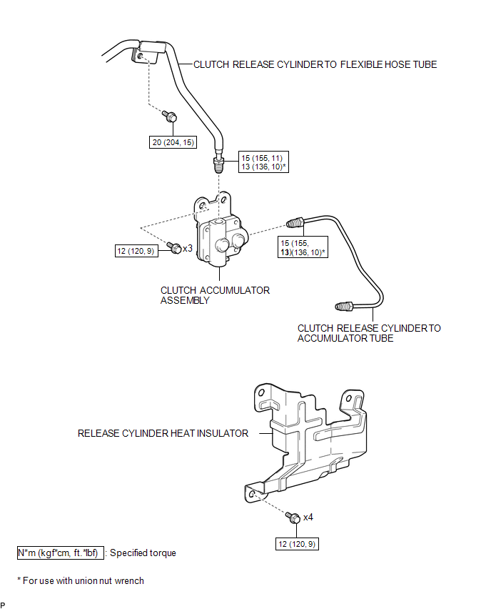
COMPONENTS
ILLUSTRATION
Installation
INSTALLATION
PROCEDURE
1. INSTALL CLUTCH ACCUMULATOR ASSEMBLY
(a) Install the clutch accumulator assembly to the manual transmission assembly with the 3 bolts.
Torque:
12 N·m {120 kgf·cm, 9 ft·lbf}
(b) Using a union nut wrench, connect the clutch release cylinder to flexible hose tube to the clutch accumulator assembly.
Torque:
Specified tightening torque :
15 N·m {155 kgf·cm, 11 ft·lbf}
HINT:
- Calculate the torque wrench reading when changing the fulcrum length
of the torque wrench (See page
.gif) ).
). - When using a union nut wrench (fulcrum length of 22 mm (0.866 in.)) + torque wrench (fulcrum length of 162 mm (6.38 in.)): 13 N*m (136 kgf*cm, 10 ft.*lbf)
(c) Install the clutch release cylinder to flexible hose tube to the manual transmission assembly with the bolt.
Torque:
20 N·m {204 kgf·cm, 15 ft·lbf}
2. INSTALL CLUTCH RELEASE CYLINDER TO ACCUMULATOR TUBE
3. INSTALL RELEASE CYLINDER HEAT INSULATOR
4. INSTALL FRONT PROPELLER SHAFT ASSEMBLY
(See page )
5. FILL RESERVOIR WITH BRAKE FLUID
6. BLEED CLUTCH LINE
7. CHECK FLUID LEVEL IN RESERVOIR
8. INSPECT FOR CLUTCH FLUID LEAK
Removal
REMOVAL
PROCEDURE
1. DRAIN CLUTCH FLUID
2. REMOVE FRONT PROPELLER SHAFT ASSEMBLY
(See page .gif) )
)
3. REMOVE RELEASE CYLINDER HEAT INSULATOR
4. REMOVE CLUTCH RELEASE CYLINDER TO ACCUMULATOR TUBE
5. REMOVE CLUTCH ACCUMULATOR ASSEMBLY
|
(a) Using a union nut wrench, disconnect the clutch release cylinder to flexible hose tube from the clutch accumulator assembly. HINT: Use a container to catch the fluid. |
|

(b) Remove the bolt and separate the clutch release cylinder to flexible hose tube from the manual transmission assembly.
|
(c) Remove the 3 bolts and clutch accumulator assembly from the manual transmission assembly. |
|

 Clutch
...
 Clutch Master Cylinder
Components
COMPONENTS
ILLUSTRATION
Installation
INSTALLATION
PROCEDURE
1. INSTALL CLUTCH MASTER CYLINDER ASSEMBLY
(a) Install the clutch master cylinder assembly to the clutch pedal suppo ...
Other materials:
Illumination Circuit
DESCRIPTION
Power is supplied to the navigation receiver assembly and steering pad switch
assembly illumination when the light control switch is in the TAIL or HEAD position.
WIRING DIAGRAM
CAUTION / NOTICE / HINT
NOTICE:
The vehicle is equipped with a Supplemental Restraint System ...
Wireless Charger Illumination Circuit
DESCRIPTION
When the light control switch is turned to the tail or head position, this circuit
sends an illumination signal to the mobile wireless charger cradle assembly. Based
on this signal, the mobile wireless charger cradle assembly dims the indicator lights
(green and amber).
WIRING DI ...
Fuel information
Your vehicle must use only unleaded gasoline.
Select octane rating 87 (Research Octane Number 91) or higher. Use of unleaded
gasoline with an octane rating lower than 87 may result in engine knocking. Persistent
knocking can lead to engine damage.
At minimum, the gasoline you use should meet t ...
