Toyota Tacoma (2015-2018) Service Manual: Voice Recognition Microphone Disconnected (B1579)
DESCRIPTION
The radio and display receiver assembly and telephone microphone assembly are connected to each other using the microphone connection detection signal lines.
This DTC is stored when a microphone connection detection signal line is disconnected.
|
DTC Code |
DTC Detection Condition |
Trouble Area |
|---|---|---|
|
B1579 |
Telephone microphone signal is lost. |
|
WIRING DIAGRAM

PROCEDURE
|
1. |
INSPECT RADIO AND DISPLAY RECEIVER ASSEMBLY |
(a) Remove the radio and display receiver assembly with connectors still connected.
|
(b) Measure the resistance according to the value(s) in the table below. Standard Resistance:
|
|

| NG | .gif) |
REPLACE RADIO AND DISPLAY RECEIVER ASSEMBLY |
|
.gif)
|
2. |
CHECK HARNESS AND CONNECTOR (RADIO AND DISPLAY RECEIVER ASSEMBLY - TELEPHONE MICROPHONE ASSEMBLY) |
(a) Disconnect the R31 radio and display receiver assembly connector.
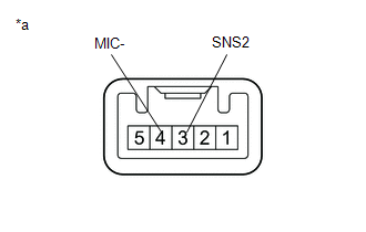
(b) Disconnect the T26 telephone microphone assembly connector.
(c) Measure the resistance according to the value(s) in the table below.
Standard Resistance:
|
Tester Connection |
Condition |
Specified Condition |
|---|---|---|
|
R31-6 (SNS2) - T26-3 (SNS2) |
Always |
Below 1 Ω |
|
R31-19 (MIN-) - T26-4 (MIC-) |
Always |
Below 1 Ω |
|
R31-6 (SNS2) - Body ground |
Always |
10 kΩ or higher |
|
R31-19 (MIN-) - Body ground |
Always |
10 kΩ or higher |
| NG | |
REPAIR OR REPLACE HARNESS OR CONNECTOR |
|
|
3. |
INSPECT TELEPHONE MICROPHONE ASSEMBLY |
(a) Remove the telephone microphone assembly.
|
(b) Measure the resistance according to the value(s) in the table below. Standard Resistance:
|
|
| OK | |
REPLACE RADIO AND DISPLAY RECEIVER ASSEMBLY |
| NG | |
REPLACE TELEPHONE MICROPHONE ASSEMBLY |
 Sending Malfunction (Navigation to APGS) (U0073,U0100,U0140,U0155)
DESCRIPTION
These DTCs are stored when a malfunction occurs in the CAN communication circuit.
DTC No.
DTC Detection Condition
Trouble Area
U0073
...
 Satellite Radio Broadcast cannot be Received
CAUTION / NOTICE / HINT
NOTICE:
Some satellite radio broadcasts require payment. A contract must be
made between a satellite radio company and the user. If the contract expires,
it w ...
Other materials:
Pressure Control Solenoid "B" Circuit Open (P077513)
DESCRIPTION
Changing from 1st to 6th is performed by the ECM turning shift solenoid valves
SL1, SL2, SL3 and SL4 on and off. If an open or short circuit occurs in any of the
shift solenoid valves, the ECM controls the remaining normal shift solenoid valves
to allow the vehicle to be operated ...
Vehicle Information Not Obtained (C1A02)
DESCRIPTION
When a new millimeter wave radar sensor assembly is installed, it receives vehicle
specification information from the main body ECU (multiplex network body ECU) and
stores the information.
DTC C1A02 is stored when the millimeter wave radar sensor assembly receives the
vehicle spe ...
Precaution
PRECAUTION
1. PRECAUTIONS WHEN USING TECHSTREAM
(a) When using the Techstream to troubleshoot the engine immobiliser system:
Connect the Techstream to the DLC3 while the ignition switch is off, and turn
a door courtesy light switch on and off at 1.5-second intervals until communication
betwee ...
