Toyota Tacoma (2015-2018) Service Manual: Removal
REMOVAL
PROCEDURE
1. REMOVE NO. 2 ENGINE UNDER COVER SUB-ASSEMBLY (w/ Off Road Package)
2. REMOVE NO. 1 ENGINE UNDER COVER SUB-ASSEMBLY
3. DRAIN ENGINE COOLANT
.gif)
4. REMOVE RADIATOR GRILLE
(See page )
5. REMOVE V-BANK COVER SUB-ASSEMBLY
6. REMOVE RADIATOR SUPPORT TO FRAME SEAL
7. REMOVE RADIATOR SIDE DEFLECTOR LH
|
(a) Remove the clip. |
|

(b) Disengage the 3 claws and remove the radiator side deflector LH.
8. REMOVE RADIATOR SIDE DEFLECTOR RH
|
(a) Remove the clip. |
|

(b) Disengage the 3 claws and remove the radiator side deflector RH.
9. REMOVE NO. 1 RADIATOR HOSE
|
(a) Slide the 2 hose clips and remove the No. 1 radiator hose from the water outlet and radiator assembly. |
|
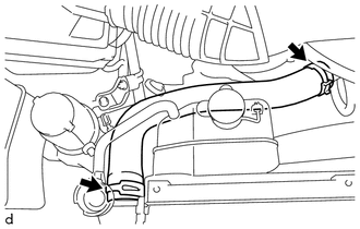
10. REMOVE NO. 2 RADIATOR HOSE
|
(a) Slide the hose clip and disconnect the No. 2 radiator hose from the water inlet with thermostat sub-assembly. |
|

|
(b) Slide the hose clip and remove the No. 2 radiator hose from the radiator assembly. |
|

11. DISCONNECT RADIATOR RESERVE TANK HOSE
|
(a) Disconnect the radiator reserve tank hose from the radiator assembly. |
|

12. DISCONNECT TRANSMISSION OIL COOLER HOSE (for Automatic Transmission)
(a) w/o Air Cooled Transmission Oil Cooler:
|
(1) Disengage the clamp to separate the 2 transmission oil cooler hoses from the fan shroud. |
|

(2) Slide the 2 hose clips and disconnect the 2 transmission oil cooler hoses from the radiator assembly.
(b) w/ Air Cooled Transmission Oil Cooler:
|
(1) Disengage the clamp to separate the 2 transmission oil cooler hoses from the fan shroud. |
|

(2) Slide the 2 hose clips and disconnect the 2 transmission oil cooler hoses from the radiator assembly.
13. REMOVE FAN SHROUD
|
(a) Loosen the 4 nuts holding the fan with fluid coupling. |
|

(b) Remove the fan and generator V belt (See page
).
|
(c) Remove the 2 bolts holding the fan shroud. |
|

(d) Remove the 4 nuts of the fan with fluid coupling, and then remove the fan shroud together with the fan with fluid coupling.
NOTICE:
Be careful not to damage the radiator core.
(e) Remove the fan pulley from the engine water pump assembly.
14. REMOVE RADIATOR ASSEMBLY
|
(a) Remove the 4 bolts. Text in Illustration
|
|

(b) Disengage the 2 hooks and remove the radiator assembly from the radiator support sub-assembly.
 Disassembly
DISASSEMBLY
PROCEDURE
1. REMOVE RADIATOR DRAIN COCK PLUG
(a) Remove the radiator drain cock plug from the radiator assembly.
(b) Remove the O-ring from the radiator drain cock plug.
2. REMOVE RAD ...
 Inspection
INSPECTION
PROCEDURE
1. INSPECT RADIATOR CORE SUB-ASSEMBLY
Check the core plate for damage.
Text in Illustration
*1
Core Plate
*2
Radiator Core
...
Other materials:
Rear Left Center Sensor Malfunction (C1AE7)
DESCRIPTION
The No. 1 ultrasonic sensor (rear center sensor LH) is installed on the rear
bumper. The ECU detects obstacles based on signals received from the No. 1 ultrasonic
sensor (rear center sensor LH). If the No. 1 ultrasonic sensor (rear center sensor
LH) has an open circuit or other ma ...
Invalid Data Received from Deceleration Sensor (C1442,C1443)
DESCRIPTION
The airbag sensor assembly has a built-in yaw rate and acceleration sensor.
The skid control ECU (brake actuator assembly) receives signals from the yaw
rate and acceleration sensor (airbag sensor assembly) via the CAN communication
system.
DTC No.
Detection ...
Removal
REMOVAL
CAUTION / NOTICE / HINT
NOTICE:
If one of the camshaft timing gear bolts is already removed, do not remove any
other camshaft timing gear bolts.
PROCEDURE
1. REMOVE NO. 2 ENGINE UNDER COVER SUB-ASSEMBLY (w/ Off Road Package)
2. REMOVE NO. 1 ENGINE UNDER COVER SUB-ASSEMBLY
3. REMOVE ...
