Toyota Tacoma (2015-2018) Service Manual: Removal
REMOVAL
PROCEDURE
1. REMOVE FRONT PILLAR GARNISH LH
(See page .gif) )
)
2. REMOVE ASSIST GRIP SUB-ASSEMBLY
(See page )
3. REMOVE FRONT PILLAR GARNISH RH
(See page )
4. REMOVE NO. 1 INSTRUMENT PANEL SPEAKER PANEL SUB-ASSEMBLY
(See page )
5. REMOVE NO. 2 INSTRUMENT PANEL SPEAKER PANEL SUB-ASSEMBLY
(See page )
6. REMOVE FRONT NO. 2 SPEAKER ASSEMBLY LH
(a) Remove the 2 bolts.
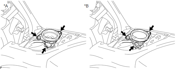 Text in Illustration
|
*A |
w/o Amplifier Box Speaker Assembly |
*B |
w/ Amplifier Box Speaker Assembly |
(b) Disconnect the connector to remove the front No. 2 speaker assembly LH.
NOTICE:
Do not touch the cone part of the front No. 2 speaker assembly LH.
7. REMOVE FRONT NO. 2 SPEAKER ASSEMBLY RH
(a) Remove the 2 bolts.
 Text in Illustration
|
*A |
w/o Amplifier Box Speaker Assembly |
*B |
w/ Amplifier Box Speaker Assembly |
(b) Disconnect the connector to remove the front No. 2 speaker assembly RH.
NOTICE:
Do not touch the cone part of the front No. 2 speaker assembly RH.
 Components
COMPONENTS
ILLUSTRATION
ILLUSTRATION
...
 Inspection
INSPECTION
PROCEDURE
1. INSPECT FRONT NO. 2 SPEAKER ASSEMBLY
(a) When there is a malfunction such as noise from a speaker or no sound at all,
replace the speaker with a new one and check that the ...
Other materials:
Components
COMPONENTS
ILLUSTRATION
*1
FRONT FENDER LINER
*2
FRONT NO.1 WHEEL OPENING EXTENSION PAD
*3
FOG LIGHT UNIT
-
-
...
Open Circuit in IG1/IG2 Power Source Circuit (C1242)
DESCRIPTION
If there is a problem with the skid control ECU (master cylinder solenoid) power
supply circuit, the skid control ECU outputs the DTC and prohibits operation under
the fail safe function.
If the voltage supplied to terminal IG1 and/or IG2 is not within the DTC detection
threshold ...
Installation
INSTALLATION
PROCEDURE
1. INSTALL HYDRAULIC BRAKE BOOSTER
(a) Install a new brake booster gasket onto the hydraulic brake booster.
(b) Install the hydraulic brake booster with the 4 nuts.
Torque:
14 N·m {145 kgf·cm, 10 ft·lbf}
(c) Using a union nut wrench, connect the 4 brake l ...
