Toyota Tacoma (2015-2018) Service Manual: Removal
REMOVAL
PROCEDURE
1. PRECAUTION
NOTICE:
After turning the ignition switch off, waiting time may be required before disconnecting the cable from the negative (-) battery terminal.
Therefore, make sure to read the disconnecting the cable from the negative (-) battery terminal notices before proceeding with work.
Click here .gif)
2. DISCONNECT CABLE FROM NEGATIVE BATTERY TERMINAL
NOTICE:
When disconnecting the cable, some systems need to be initialized after the cable is reconnected.
Click here
3. REMOVE REAR WHEEL
4. DRAIN BRAKE FLUID
5. REMOVE REAR BRAKE DRUM SUB-ASSEMBLY
Click here
6. REMOVE FRONT BRAKE SHOE
Click here
7. REMOVE REAR BRAKE SHOE
Click here
8. REMOVE REAR SPEED SENSOR
Click here
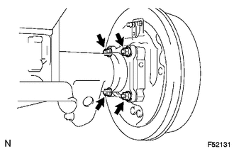
9. SEPARATE PARKING BRAKE CABLE ASSEMBLY NO. 3

(a) Remove the 2 bolts and disconnect the parking brake cable from the backing plate.
10. SEPARATE REAR BRAKE TUBE NO. 8

(a) Using a union nut wrench, separate the brake tube, and use a container to catch the brake fluid as it flows out.
11. REMOVE REAR AXLE SHAFT WITH BACKING PLATE
(a) Remove the 4 nuts and rear axle shaft with backing plate.
(b) Remove the O-ring.
12. REMOVE REAR AXLE SHAFT OIL SEAL

(a) Using SST, remove the oil seal.
SST: 09308-00010
 Inspection
INSPECTION
PROCEDURE
1. INSPECT REAR AXLE SHAFT
(a) Using a dial indicator, measure the runout of the shaft and flange.
Maximum runout:
Shaft runout: 1.5 mm (0.0591 in.)
Flange runout: 0.05 m ...
 Installation
INSTALLATION
PROCEDURE
1. INSTALL REAR AXLE SHAFT OIL SEAL
(a) Using SST and a hammer, install a new oil seal.
SST: 09950-60020
09951-00770
SST: 09950-70010
09951-07150
2. INSTALL REAR AXLE ...
Other materials:
Main Switch Signal Circuit
DESCRIPTION
When the wireless charger main switch (mobile wireless charger switch) is turned
on, this circuit sends an on signal to the mobile wireless charger cradle assembly
using the power supplied to the wireless charger main switch (mobile wireless charger
switch).
WIRING DIAGRAM
CAU ...
Components
COMPONENTS
ILLUSTRATION
*A
w/o Navigation System
*B
w/ Navigation System
*C
for Double Cab
*D
for Acces Cab
*E
for 4WD
-
-
*1
...
On-vehicle Inspection
ON-VEHICLE INSPECTION
PROCEDURE
1. CHECK STEERING WHEEL FREE PLAY
(a) Stop the vehicle and align the tires facing straight ahead.
(b) Gently turn the steering wheel right and left by hand, and check
the steering wheel free play.
Maximum free play:
30 mm (1.18 in.)
Text i ...
