Toyota Tacoma (2015-2018) Service Manual: Rear Power Outlet Switch
Components
COMPONENTS
ILLUSTRATION

Inspection
INSPECTION
PROCEDURE
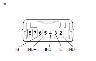
1. INSPECT MAIN SWITCH ASSEMBLY
(a) Check the main switch assembly.
|
(1) Measure the resistance according to the value(s) in the table below. Text in Illustration
Standard Resistance:
|
|
(b) Check the switch indicator.
(1) Apply battery voltage to the main switch assembly and check that the switch indicator illuminates.
OK:
|
Measurement Condition |
Switch Condition |
Specified Condition |
|---|---|---|
|
Battery positive (+) → 5 (IND+) Battery positive (-) → 2 (IND-) |
Always |
Illuminates |
OK:
|
Measurement Condition |
Switch Condition |
Specified Condition |
|---|---|---|
|
Battery positive (+) → 6 (IG) Battery positive (-) → 4 (IND) |
Always |
Illuminates |
- If the specified condition is not met, replace the main switch assembly.
Removal
REMOVAL
PROCEDURE
1. REMOVE INSTRUMENT PANEL LOWER FINISH PANEL SUB-ASSEMBLY RH
(See page .gif) )
)
2. REMOVE MAIN SWITCH ASSEMBLY
|
(a) Disengage the 2 claws to remove the main switch assembly. |
|

Installation
INSTALLATION
PROCEDURE
1. INSTALL MAIN SWITCH ASSEMBLY
(a) Engage the 2 claws to install the main switch assembly.
2. INSTALL INSTRUMENT PANEL LOWER FINISH PANEL SUB-ASSEMBLY RH
(See page .gif) )
)
 Rear Power Outlet Socket
Components
COMPONENTS
ILLUSTRATION
ILLUSTRATION
Installation
INSTALLATION
PROCEDURE
1. INSTALL POWER OUTLET SOCKET ASSEMBLY
(a) Install the clamp.
(b) Connect the connector.
...
 Voltage Inverter
Components
COMPONENTS
ILLUSTRATION
Inspection
INSPECTION
PROCEDURE
1. INSPECT VOLTAGE INVERTER ASSEMBLY
(a) Check the voltage inverter assembly.
(1) Measure the voltage according to the ...
Other materials:
Definition Of Terms
DEFINITION OF TERMS
Term
Definition
Monitor Description
Description of what the ECM monitors and how it detects malfunctions
(monitoring purpose and details).
Related DTCs
A group of diagnostic trouble codes that are ...
A/C ECU Vehicle Information Reading/Writing Processor Malfunction (B15F5)
DESCRIPTION
This DTC is stored when items controlled by the air conditioning amplifier assembly
cannot be customized via the audio and visual system vehicle customization screen.
HINT:
The air conditioning amplifier assembly controls the air conditioning system
related items that are customiz ...
Microphone Circuit between Microphone and Radio Receiver
DESCRIPTION
The navigation receiver assembly and telephone microphone assembly are connected
to each other using the microphone connection detection signal lines.
Using this circuit, the navigation receiver assembly sends power to the telephone
microphone assembly and the telephone microphone ...
