Toyota Tacoma (2015-2018) Service Manual: Inspection
INSPECTION
PROCEDURE
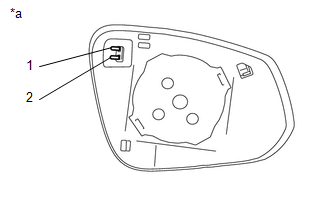
1. INSPECT OUTER MIRROR LH
|
(a) Check the outer mirror heater operation. Text in Illustration
(1) Measure the resistance according to the value(s) in the table below. Standard Resistance:
If the result is not as specified, replace the outer mirror LH. |
|

|
(b) Check the operation of the outer rear view mirror indicator. (w/ Blind Spot Monitor) Text in Illustration
(1) Apply 6 V battery voltage to the terminals of the connector, and check that the outer rear view mirror indicator comes on. NOTICE: Do not apply a voltage of more than 6 V. HINT: Connect 4 new 1.5 V dry-cell batteries in series. OK:
If the result is not as specified, replace the outer mirror LH. |
|

2. INSPECT OUTER MIRROR RH
|
(a) Check the outer mirror heater operation. Text in Illustration
(1) Measure the resistance according to the value(s) in the table below. Standard Resistance:
If the result is not as specified, replace the outer mirror RH. |
|
|
(b) Check the operation of the outer rear view mirror indicator. (w/ Blind Spot Monitor) Text in Illustration
(1) Apply 6 V battery voltage to the terminals of the connector, and check that the outer rear view mirror indicator comes on. NOTICE: Do not apply a voltage of more than 6 V. HINT: Connect 4 new 1.5 V dry-cell batteries in series. OK:
If the result is not as specified, replace the outer mirror RH. |
|
3. INSPECT OUTER REAR VIEW MIRROR ASSEMBLY LH
|
(a) Check the operation of the mirror surface. Text in Illustration
(1) Apply battery voltage and check the operation of the mirror. OK:
If the result is not as specified, replace the outer rear view mirror assembly LH. |
|

|
(b) Check the side turn signal light assembly LH. Text in Illustration
(1) Apply battery voltage to the terminals of the connector, and check the illumination condition. OK:
If the result is not as specified, replace the outer rear view mirror assembly LH. |
|

|
(c) Check the operation of the mirror heater. Text in Illustration
(1) Measure the resistance according to the value(s) in the table below. Standard Resistance:
If the result is not as specified, replace the outer rear view mirror assembly LH. (2) Connect the cable from the positive (+) battery terminal to terminal 2 (+) and the negative (-) battery terminal to terminal 8 (-), and then check that the mirror becomes warm. HINT: It takes a short time for the mirror to become warm. OK: Mirror becomes warm. If the result is not as specified, replace the outer rear view mirror assembly LH. |
|

|
(d) Check the operation of the BSM. Text in Illustration
(1) Apply 6 V dry-cell battery voltage to the terminals of the connector, and check the illumination condition. NOTICE: Do not apply a voltage of 6 V or higher. HINT: Connect the 1.5 V 4 pieces batteries of a new series, applying a 6 V voltage of between each terminal of the connector. OK:
If the result is not as specified, replace the outer rear view mirror assembly LH. |
|

4. INSPECT OUTER REAR VIEW MIRROR ASSEMBLY RH
|
(a) Check the operation of the mirror surface. Text in Illustration
(1) Apply battery voltage and check the operation of the mirror. OK:
If the result is not as specified, replace the outer rear view mirror assembly RH. |
|

|
(b) Check the side turn signal light assembly RH. Text in Illustration
(1) Apply battery voltage to the terminals of the connector, and check the illumination condition. OK:
If the result is not as specified, replace the outer rear view mirror assembly RH. |
|
|
(c) Check the operation of the mirror heater. Text in Illustration
(1) Measure the resistance according to the value(s) in the table below. Standard Resistance:
If the result is not as specified, replace the outer rear view mirror assembly RH. (2) Connect the cable from the positive (+) battery terminal to terminal 2 (+) and the negative (-) battery terminal to terminal 8 (-), and then check that the mirror becomes warm. HINT: It takes a short time for the mirror to become warm. OK: Mirror becomes warm. If the result is not as specified, replace the outer rear view mirror assembly RH. |
|
|
(d) Check the operation of the BSM. Text in Illustration
(1) Apply 6 V dry-cell battery voltage to the terminals of the connector, and check the illumination condition. NOTICE: Do not apply a voltage of 6 V or higher. HINT: Connect the 1.5 V 4 pieces batteries of a new series, applying a 6 V voltage of between each terminal of the connector. OK:
If the result is not as specified, replace the outer rear view mirror assembly RH. |
|
 Disassembly
DISASSEMBLY
CAUTION / NOTICE / HINT
HINT:
Use the same procedures for both the LH and RH sides.
The procedure described below is for the LH side.
PROCEDURE
1. REMOVE OUTER MIRRO ...
 Reassembly
REASSEMBLY
CAUTION / NOTICE / HINT
HINT:
Use the same procedures for both the LH and RH sides.
The procedure described below is for the LH side.
PROCEDURE
1. INSTALL SIDE TURN S ...
Other materials:
Customize Parameters
CUSTOMIZE PARAMETERS
PROCEDURE
1. CUSTOMIZE INTUITIVE PARKING ASSIST SYSTEM
(a) Customizing with the Techstream
NOTICE:
When the customer requests a change in a function, first make sure that
the function can be customized.
Be sure to make a note of the current settings before c ...
Diagnostic Trouble Code Chart
DIAGNOSTIC TROUBLE CODE CHART
VSC System
DTC Code
Detection Item
See page
C1201
Engine Control System Malfunction
C1203
ECM Communication Circuit Malfunction
C120B
...
Reassembly
REASSEMBLY
PROCEDURE
1. INSTALL INDICATOR LIGHT WIRE SUB-ASSEMBLY
(a) Connect the connector to install the indicator light wire sub-assembly
to the shift position indicator.
(b) Attach the clamp to install the indicator light wire sub ...
