Toyota Tacoma (2015-2018) Service Manual: Fuel Pressure Sensor
Components
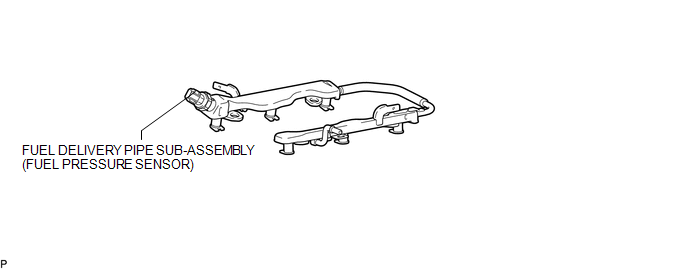
COMPONENTS
ILLUSTRATION
Inspection
INSPECTION
PROCEDURE
1. INSPECT FUEL DELIVERY PIPE SUB-ASSEMBLY (FUEL PRESSURE SENSOR)
NOTICE:
- Do not remove the fuel pressure sensor from the fuel delivery pipe sub-assembly.
- If a fuel pressure sensor is removed, replace the fuel delivery pipe sub-assembly with a new one.
(a) Remove the fuel delivery pipe sub-assembly (See page
.gif) ).
).
(b) Check the fuel pressure sensor output voltage.
|
(1) Apply 5 V between terminals 1 (VC) and 3 (E2). Text in Illustration
NOTICE:
HINT: If a stable power supply is not available, use 4 1.2 V nickel-metal hydride batteries or equivalent. |
|

|
(2) Measure the voltage between terminals. Text in Illustration
Standard Voltage:
If the result is not as specified, replace the fuel delivery pipe sub-assembly. |
|

(c) Install the fuel delivery pipe sub-assembly (See page
).
Installation
INSTALLATION
CAUTION / NOTICE / HINT
HINT:
Perform "Inspection After Repairs" after replacing the fuel delivery pipe sub-assembly
(fuel pressure sensor) (See page .gif) ).
).
PROCEDURE
1. INSTALL FUEL DELIVERY PIPE SUB-ASSEMBLY (FUEL PRESSURE SENSOR)
(See page )
NOTICE:
- Do not remove the fuel pressure sensor from the fuel delivery pipe sub-assembly.
- If a fuel pressure sensor is removed, replace the fuel delivery pipe sub-assembly (fuel pressure sensor) with a new one.
HINT:
Perform "Inspection After Repairs" after replacing the fuel delivery pipe sub-assembly
(fuel pressure sensor) (See page ).
Removal
REMOVAL
PROCEDURE
1. REMOVE FUEL DELIVERY PIPE SUB-ASSEMBLY (FUEL PRESSURE SENSOR)
(See page .gif) )
)
NOTICE:
- Do not remove the fuel pressure sensor from the fuel delivery pipe sub-assembly.
- If a fuel pressure sensor is removed, replace the fuel delivery pipe sub-assembly (fuel pressure sensor) with a new one.
 Fuel Main Valve
Components
COMPONENTS
ILLUSTRATION
Removal
REMOVAL
PROCEDURE
1. REMOVE FUEL SUCTION TUBE WITH PUMP AND GAUGE ASSEMBLY
(See page )
2. REMOVE FUEL SENDER GAUGE ASSEMBLY
3. REMOVE NO. ...

Other materials:
Emission inspection and maintenance (I/M) programs
Some states have vehicle emission inspection programs which include OBD (On
Board Diagnostics) checks. The OBD system monitors the operation of the emission
control system.
■ If the malfunction indicator lamp comes on
The OBD system determines that a problem exists somewhere in the emiss ...
Radio Antenna Cord
Components
COMPONENTS
ILLUSTRATION
Removal
REMOVAL
PROCEDURE
1. REMOVE INSTRUMENT PANEL SUB-ASSEMBLY
(See page )
2. REMOVE ANTENNA CORD SUB-ASSEMBLY
(a) Disengage the 4 clamps to remove the antenna cord sub-assembly.
Installation
INSTALLATION
PROCEDURE
1. INSTALL ANTENNA COR ...
Disassembly
DISASSEMBLY
PROCEDURE
1. REMOVE STEERING GEAR OUTLET RETURN TUBE
(a) Using a union nut wrench, remove the steering gear outlet return tube.
2. REMOVE STEERING TURN PRESSURE TUBE
(a) Using a union nut wrench, remove the 2 pressure tubes.
(b) Remove the 4 O-rings from the pressure tubes.
3. ...
