Toyota Tacoma (2015-2018) Service Manual: Data Signal Circuit between Stereo Jack Adapter and Extension Module
DESCRIPTION
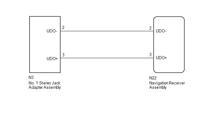
The No. 1 stereo jack adapter assembly sends the sound data signal or image data signal from a USB device to the navigation receiver assembly via this circuit.
WIRING DIAGRAM
PROCEDURE
|
1. |
CHECK HARNESS AND CONNECTOR (NAVIGATION RECEIVER ASSEMBLY - NO. 1 STEREO JACK ADAPTER ASSEMBLY) |
(a) Disconnect the N22 navigation receiver assembly connector.
(b) Disconnect the N3 No. 1 stereo jack adapter assembly connector.
(c) Measure the resistance according to the value(s) in the table below.
Standard Resistance:
|
Tester Connection |
Condition |
Specified Condition |
|---|---|---|
|
N3-2 (UDO-) - N22-2 (UDO-) |
Always |
Below 1 Ω |
|
N3-3 (UDO+) - N22-3 (UDO+) |
Always |
Below 1 Ω |
|
N3-2 (UDO-) - Body ground |
Always |
10 kΩ or higher |
|
N3-3 (UDO+) - Body ground |
Always |
10 kΩ or higher |
| OK | .gif) |
PROCEED TO NEXT SUSPECTED AREA SHOWN IN PROBLEM SYMPTOMS TABLE |
| NG | |
REPAIR OR REPLACE HARNESS OR CONNECTOR |
 Sound Signal Circuit between Radio Receiver and Stereo Component Amplifier
DESCRIPTION
The navigation receiver assembly sends a sound signal to the stereo component
amplifier assembly via this circuit.
The sound signal that has been sent is amplified by the stereo compon ...
 Sound Signal Circuit between Radio Receiver and Stereo Jack Adapter
DESCRIPTION
The No. 1 stereo jack adapter assembly sends the sound signal from an external
device to the navigation receiver assembly via this circuit.
If there is an open or short in the circuit, ...
Other materials:
Portable Player cannot be Registered
CAUTION / NOTICE / HINT
HINT:
Some versions of "Bluetooth" compatible audio players may not function, or the
function may be limited using the radio and display receiver assembly, even if the
portable audio player itself can play files (See page
).
PROCEDURE
1.
...
All Doors LOCK/UNLOCK Functions do not Operate Via Door Control Switch
DESCRIPTION
The main body ECU (multiplex network body ECU) receives switch signals from the
door control switch assembly on the front passenger door and activates the door
lock motor on each door according to these signals.
WIRING DIAGRAM
PROCEDURE
1.
READ VALUE USIN ...
Downhill Assist Control Switch Malfunction (Test Mode DTC) (C1379)
DESCRIPTION
DTC C1379 is cleared when the crawl control switch sends a crawl control operation
signal or when test mode ends.
DTC Code
DTC Detection Condition
Trouble Area
C1379
Stored only during test mode.
Crawl ...
